

Information Technology (IT) Pioneers
Retirees and former employees of Unisys, Lockheed Martin, and their heritage companies
Air Traffic Control Systems, Chapter 61
If you have flown any time since the late 50s, part of your flight
has been under the control of systems developed by Remington Rand, UNIVAC,
etc. for the Federal Aviation Administration (FAA).
These systems began with a file computer and associated
software doing simple flight strips for air traffic controllers. Then
the first Automated Radar Terminal Control System (ARTS I) in Atlanta,
GA and the FAA test facility near Atlantic City, NJ used the UNIVAC
Type 1218 computers originated by the Naval Tactical Data System to
process radar location and IFF signals.
The genealogy chart below shows the relationships
of ATC systems now in use throughout the world. Much as NTDS provided
baseline technology for ATC, the ATC technologies led to a Marine Corps
Air Traffic Control And Landing System then the Air Sovereignty Operations
Centers. There is an IOP unit on display at the S. St. Paul Lawshe Memorial
Museum.
UNIVAC - Unisys also was heavily involved with airline reservations
systems beginning in 1956 - we need an experienced volunteer to write
about those for our Systems, Commercial page.
Thanks to Tom Montgomery and his co-workers who provided the information and links for this Legacy chapter. [lab]
2. Genealogy of ATC Systems
Tom Montgomery and his co-workers created this Eagan ATC History
Genealogy, descriptions of each line of this chart are in a
four page document.
Webster defines an EPOCH as "a period marked by certain events." This genealogy chart clearly illustrates an Input Output Processor (IOP) 40-year epoch within the 50+ years of ATC systems which are within our Legacy which began at Engineering Research Associates in January of 1946. We write '50+ years' because a cadre of engineers will be supporting and enhancing Air Traffic Control systems from a Lockheed Martin 'leased' facility in the Twin Cities area well beyond the 2013 closing of the LMCO Eagan facility.
I'm quite sure that the 1970 engineering team who were designing
the IOP with logic using small scale integrated circuits [i.e. 4 bit
arithmetic chips] and a 750 nanosecond semi-conductor memory could not
have imagined that their designs would still be operational 40 years
later! My hat is off to those engineers, I recall that John Bonnes [BEE
- U of MN, 1965] was one of the logic designers implementing a variation
of the Naval Tactical Data Systems 30-bit Instruction Set Architecture.
by LABenson
3. ATC System Locations
This March 2012 chart locates the 124 US associated Operational Facilities
for which we've provided ATC systems, now operating as 'Common ARTS'
systems.
4. ATC Descriptions
 This photo shows several aircraft on final approach - ATC
systems provide the controllers with position information, flight number
and aircraft type, recommend aircraft spacing, altitudes, and speeds
as they near airports and touchdown.
These systems also provide possible
collision warnings. [lab]
This photo shows several aircraft on final approach - ATC
systems provide the controllers with position information, flight number
and aircraft type, recommend aircraft spacing, altitudes, and speeds
as they near airports and touchdown.
These systems also provide possible
collision warnings. [lab]
4.1 Hardware Information:
The initial ARTS I era ATC systems depended heavily upon hardware
available from the NTDS production lines. For your edification, we've
provided a description document
of this hardware.
ARTS III and ARTS IIIA era hardware description documents are:
Breakpoint Module, BPM;
Channel Back to Back Switch,
CBBS; Console Data Terminal,
CDT; Central Memory Access
module, CMA; Communications
Multiplexer Controller, CMC;
Disc Control Unit, DCU;
Disc Drive Unit, DDU; Data
Entry Display Subsystem, DEDS;
Interface Buffer Adapter and Generator,
IBAG; Input Output Processor-B,
IOP; Interface Sensor Receiver
And Processor, ISRAP;
Multiplexed Display Buffer Memory,
MDBM; Memory Module,
MM; Minimum Safe Altitude
Warning, MSAW; Medium Speed
Printer, MSP; Magnetic Tape
Subsystem, MTS; Processor
Module Cabinet, PCAB; Peripheral
Switch Module, PSM; 19"
Equipment Rack, Rack; Recovery
Alarm, RALM; Remote Display
Buffer Memory, RDBM; Reconfiguration
and Fault Detection Unit, RFDU;
Real Time Clock, RTC; Sensor
Receiver and Processor, SRAP;
and Solid State Memory, SSM.
![]()
4.2 Air Traffic Control Software:
The following shows a sample software functional flow diagram for our largest ARTS IIIA system, at the New York TRACON:
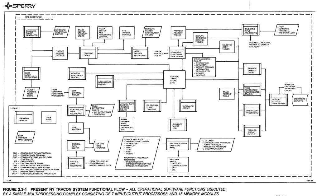
The efficient use of multiple parallel IOPB processors by the application software, highlighted in the above diagram, was made possible by the Multi-Processor Executive (MPE) software.
The description of the MPE below is lifted from the ARTS IIIA program specifications, but it doesn't do justice to the major role the MPE scheduler played in our ability to efficiently operate seven of eight IOP-Bs in a multiprocessor configuration with 256K 30-bit words of shared memory. The MPE Scheduler's lattice design, the reentrant design of the ARTS IIIA operational program and some very smart people who made this all work are the keys to the successful implementation at the larger ARTS IIIA sites, the New York TRACON ARTS IIIA system and the EARTS sites. This link takes you to a pictorial of the New York TRACON A5.04 lattice (Thanks to Marlin Jerpseth who can still interpret those Scheduler listings!).
This is the MPE description from the ARTS IIIA CPFS:
The Failsafe/Fail-soft Multiprocessor Executive (MPE) includes all Executive modules (on–line or off–line). These are the Initializer, Scheduler, Executive Services, Disc, Interrupt and the Debug. The MPE provides overall control of the Multiprocessor Data Processing Subsystem (MDPS), handles the execution of operational programs [called tasks], and is responsible for failure detection and recovery logic, I/O to the Disc, teletype, Medium Speed Printer (MSP), integral Magnetic Tape, and Communications Multiplexer Controller (CMC). Tasks have many operating needs, consisting, as a minimum, of permanent program memory, temporary program memory, common data base access, processor time, input/output (I/O) functions, execution priorities, and periodic or an a-periodic execution frequencies. In order to achieve optimum efficiency within an MDPS, task workloads must be properly distributed among the competing processors, and highly interfacing tasks must be scheduled so that simultaneous data fetches and memory accesses are minimized. This efficiency is achieved in the MPE controlled system through preplanning task execution by means of a task network, or lattice. The lattice describes all tasks which are successors to the given task. Tasks scheduled via a lattice are called planned tasks, and tasks which are scheduled a-periodically are called popup tasks. The planned task lattice provides the key to an efficient operating system.
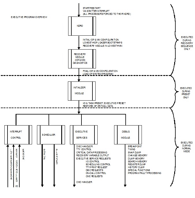
An overview of the Failsafe/Fail-soft Multi-Processor Executive software
is depicted in this diagram [right]:
Also, every good programmer kept a copy of the
IOPB repertoire card,
below, in his shirt pocket [right behind his pocket protector (full
of multicolored pencils) and a couple of 80-column punched cards for
writing notes on.]
![]()
4.3 Systems Descriptions:
- ARTS I Atlanta "Tag Your Targets.pdf "
- ARTS IA New York CIFRR "CIFRR.pdf "
- ARTS III "ARTS III.pdf "
- ARTS IIIA "ARTS IIIA.pdf "
- ARTS IIIA Tampa Sarasota "Tampa All Digital System - 2.pdf "
- ARTS IIIE "ARTS IIIE.pdf "
- China ASTEC "ASTEC.pdf "
- Common ARTS and ARTS Color Display “Common ARTS mr.pdf” and “ARTS Color Display mr.pdf "
- Denver Final Monitor Aid "FMA.pdf "
- EARTS "EARTS Color.pdf "
- En Route Automated Radar Terminal system Target Generator Quick Reference
- File Computer Enroute System "Computers and the Airways.pdf "
- German STCA "STCA.pdf "
- Japanese ARTS "Japanese ARTS.pdf "
- Korean ARTS "Kimpo Korea ARTSIII.pdf "
- MATCALS "MATCALS.pdf "
- Micro-EARTS "Micro-EARTS mr.pdf "
- Murphy Dome "Murphy Dome libr 3310.pdf "
- New York TRACON ARTS IIIA "NY TRACON ARTS IIIA - 2.pdf "
- NYCBAN The New York Center Beacon Alpha Numeric (NYCBAN) system was simply a relocation of the SPAN system from the Indianapolis Center and site adapted for the New York Center at Ronkonkoma, Long Island. "Tag Your Targets – No 2.pdf "
- SPAN "Tag Your Targets – No 2.pdf "
- Taiwan ATCAS "Taiwan ATCAS.pdf "
4.4 Documents Available to Peruse:
- A 1963 article by Jay Rabb.
- The 1964 File Computer application description.
- A 1964 article by Jay Rabb and Al Ridenour.
- A 1967 article by Robert Anderson.
- A 1971 Automated Air Traffic Control re-print by Jack Sater, et al.
- A 1972 Air Traffic Control Experience re-print by R.J. Hansen.
- A 1990 History of Terminal Automation by the ATC staff.
4.5 Associated sites:
The FAA Website
also provide relevant information.
![]()
5.0 ZKSD
From Glen Hambleton, written February 2023: Glen wrote about his trials and difficulties in getting ZKSD proposed, see Our Stories #305. This was not the German STCA shown in section 2 above,1995 time frame.
From Dick Lundgren's European Business Article via Lowell:
"However, in the non-Navy area, the company had some other notable
business accomplishments, specifically for the German equivalent of
the FAA. In 1976 Sperry Univac-Eagan and Sperry Univac-Germany jointly
performed on a contract called ZKSD with the German Air Traffic Control
Agency (BFS) to develop a central Flight Data Processing (FDP) system
that would distribute and print flight strips at all civilian airports
in West Germany. ZKSD stands for Zentraler Kontroll Streifen Druck (literally,
Central Control Strip Printing, or more descriptively, Central Flight
Plan Data Processing and Strip Printing System). BFS is the Bundesanstalt
für Flug Sicherung (Federal Institute for Flight Safety). The initial
architecture utilized multi-IOP computers from the US-FAA programs but
as the architecture matured, main frame commercial 1100 series processors
were used. Unisys Germany continued to support this system including
a major upgrade called UKD into the late 1990s."
From Larry Bolton:
Wed, 12 Oct 2011 10:59:41 -0500 - In looking at photos yesterday, I came across a photo of some cards I had not seen before. They are 56 pin. But rather than the more normal nearly square shape, these were elongated - still only 56 pins wide but about 50% taller. I had never seen these before. They are about 1978 vintage.
After asking about and doing some tracking, we determined they might have something to do with a program called ZKSD or a CMA requestor kit. There was also a photo of a frame which would hold these cards. Neither photo had any labeling to indicate what it was.
From Harvey Taipale: ZKSD was a one of-a-kind system for Germany, Project Engineer was Ed Temmers. This iteration of the system never worked to the German’s satisfaction, and I believe the program was switched to commercial processors, which did not use the CMA.
ARTS IIIA had a box called the Central Memory Access Unit, which indeed did use elongated 56 pin cards with DIPs on it. CMA was a memory multiplexer, allowing scalable systems of up to 8 IOP’s talk to up to 16 memory modules (all 16K x 32 bits, core, made by Dataproducts). The main ARTS processing system was built from these modules and a box called the Reconfiguration and Fault Detection Unit (RFDU). Any system error would trigger a “scatter” interrupt, suspending ATC processing and driving every unit into a self test mode. All good units would then reconfigure around any failing units and resume ATC processing, all within 10 seconds. CMA was the traffic cop for memory accesses, and unfortunately proved to have noise and multi-stable priority problems, causing many scatter interrupts and earning the controllers distrust. The unit was redesigned and worked fairly well thereafter, although the multi-stable problems were never completely eliminated. I recall this vividly, as I had just inherited the ATC hardware project engineer’s role when this problem surfaced.
Original CMA design was done by Merlyn Alexander, working or Pete Tierney on an FAA R&D contract. Redesign was done by a ”team” led by Gerry Griffith and Verle Christianson, but the real work was done by Doug Hair and Jerry Thibideau.
From Larry Bolton: Thanks Harvey, I think you have it.
One of the photos appears to show a 7501375 Requester Data Multiplexer card in three stages. The first appears to be the card as initially released. Apparently there was a problem with one of the signal traces on the card because a second photo shows the same card but with a short piece of coax shielded cable going from one circuit to another. This must have worked because the third photo shows an engineering version of the same card but a ground plane has been added to the top side of the printed wiring board.
You are correct that the circuits on the card are DIPs. I believe the CMA nomenclature is on the photo. The ZKSD term came when we tried to get a used-on for the part number. Thanks to all for the assistance.
In this Chapter
- Introduction [left]
- Genealogy of ATC Systems
- ATC Locations
- ATC Descriptions.
- Hardware Information
- Air Traffic Control Software
- Systems Descriptions
- Documents Available to Peruse
- Associated Sites
- ZKSD a Germany system.
Chapter 61 edited 7/13/2025.

![]() |
Home, Pg 1 |
Our Legacy, Ch 1 |
People |
Locations |
Engineered |
Computers |
Systems |
Contacts and Links |
Site Map, Pg 0 |
|
Home, Pg 1 |
Our Legacy, Ch 1 |
People |
Locations |
Engineered |
Computers |
Systems |
Contacts and Links |
Site Map, Pg 0 |
Copyright ©2025, LABenson for the VIP Club. All Rights Reserved; Hosted on www.webhostinghub.com since 2011.