

Information Technology (IT) Pioneers
Retirees and former employees of Unisys, Lockheed Martin, and their heritage companies
Engineering Introduction, Chapter 40
In addition to enginering computers and systems; in order to field practical, reliable operational systems; we also developed and delivered many peripheral devices and communications equipments. We supported these in the field. Our programmers and engineers developed test, support, and operational software. Our equipments were assigned UNIVAC/Sperry type numbers and in many cases a military nomenclature - A summary card is available.
Engineering details are in the topical chapters:
- Chapter 41, Antenna Couplers plus other early ERA and UNIVAC products/devices by Marc Shoquist, et al.
- Chapter 42, Component Engineering by Larry Bolton and Mike Svendsen.
- Chapter 43, Field Service Engineering by Dick Roessler
- Chapter 44, Interfaces/Network Engineering - by Marc Shoquist, John Nemanich, and Lowell Benson.
-
 Chapter
45, Memory Engineering; drum memory, braided wire, bubble memory units, plated
wire, film memory - by Bolton, Howe, Dick Petschauer, and Benson.
Chapter
45, Memory Engineering; drum memory, braided wire, bubble memory units, plated
wire, film memory - by Bolton, Howe, Dick Petschauer, and Benson.
- Chapter 46, Patents by several engineers
- Chapter 47, Peripheral Equipment Engineering by Dick Kuhns, et al.
- Chapter 48, Software Engineering by John Byrne, et al.
- Chapter 49, Training by Lyle Franklin
2. History tidbits from Frank Kline
I had a small ERA engineering group doing circuit design
but there is little paper trail available.
Adi Khambata worked for me and did original work on integrated circuits
working with people at T.I., Motorola, and Fairchild. Adi wrote the first
book on Integrated circuits and it was printed for UNIVAC marketing
and given to people all over the government. Adi also was the first
one I know who published a book using a computer and submitted the text
to the publisher on floppy disk. Adi was in charge of a radiation lab
reporting to me where he directed tests on simulated nuclear weapon effects
or radiation hardness design of computer circuits. The lab used a flash x-ray
in a shielded screen room to test integrated circuits. We were among
the first to work on radiation effects. Much of the work in those days
was sponsored by Internal Research and Development and reported to the
government.
Lenard Corkey Pollick was responsible for the ERA bore hole camera project under Howard Daniels. Corkey was a physicist and made all the optics for many of our projects. Frank Kline
3. Design and Drafting of Printed Circuit Boards by Bob Langer
Where would a computer company be without a key ingredient for its
success such as the Printed Circuit Board (PCB)? Of course it would
not exist. The design of the PCB artwork patterns, the supporting documentation
and the tooling used to manufacture and assemble PCB’s must be
cost effective, very accurate and with fast turnaround.
I was hired in 1957 by Remington Rand Univac and retired in 2001 with
the same company now called Lockheed Martin. I was in the same Design
and Drafting organization for my entire career of nearly 44 years. This
includes two years of military leave in the U.S. Navy aboard the very
popular tourist attraction the U.S.S. Intrepid, a WWII aircraft carrier,
which currently rests in a New York City harbor as a museum. It attracts
over 750,000 visitors annually.
My educational background was one year at the University of Wisconsin
River Falls in a pre-engineering course prior to employment and during
employment I received a Certificate of Completion in Electronics after
3 years of night classes at St Paul Vo-Tech.
My career started as a draftsman working primarily with
the design of PCB artwork patterns from circuit sketches designed by
electrical engineers. In the early days we used black masking tape 1/8”
wide and 3/8” round donuts or pads to create the circuit pattern
for the artwork at a scale of 4:1 which would be photo reduced to 1:1
by the factory. That artwork photo tooling was used to etch the circuit
pattern on copper clad board material. I would estimate hundreds of
artwork patterns for many projects were developed by our PC Design Group
for fabrication and assembly by our own factory during my career.
A very significant advance in the development of PCB artwork
patterns came with the new age of drafting automation called Computer
Aided Design (CAD.) In the 1970’s Earl Vraa’s Software Group
developed the software capability for drafting to input the electrical
engineer’s schematic sketch into our company mainframe computers
to automatically route circuit lines and generate artwork patterns for
multilayer PCB’s. It also provided associated schematic and related
drawings to fabricate and assemble circuit cards. I always felt this
software provided our company a very competitive edge giving us the
advantage over other computer companies to win major defense contracts
such as AN/UYK-43 and other major projects. At that time I was responsible
for the PC Design Group that did all the artwork designs and documentation
for our Defense Systems organization. I would venture to say the peak
workload for our group came in the1980’s during the design and
development of projects for AN/UYK-43 and AN/UYK-44 computers. This
was also the startup of integrated circuit design and development within
the PC Design Group. I was responsible for 55 people in this new PC/IC
Design Group including the photo lab area which produced the glass plate
tooling and provided coordination with manufacturing. The IC Design
portion of the group separated to become part of the new semiconductor
facility during this period. In the 1990’s the PC Design Group
started using personal computers with proven vendor supplied PC design
software required for the very complex PC designs. These new designs
using complex integrated circuits significantly reduced the overall
quantities of circuit cards needed for a project causing a reduction
in drafting personnel, the closing of our manufacturing facility and
was my time to retire.
Overall I had a real interesting career experience going
from a manual operation with a large number of great hard working people
to a totally automated group requiring only a few highly skilled PC
Designers using outside vendors for manufacture. I still meet monthly
for lunch discussions with the retired designers and engineers and enjoy
playing golf with them quite regularly. Bob Langer
4. Maintenance Panels by Larry Bolton
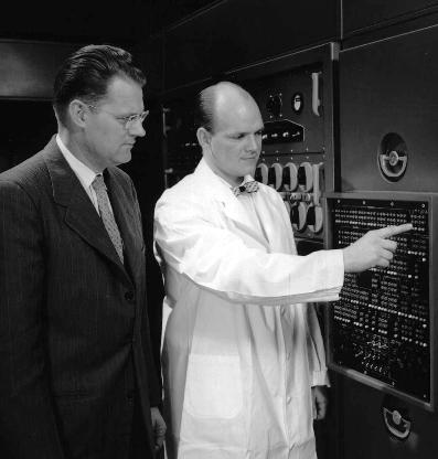
Before computer TV-type display screens,
early computers had large front panels with many lights.
 This was the
most visible part of the computer and, aside of the spinning tape reels,
was where the action was.
This was the
most visible part of the computer and, aside of the spinning tape reels,
was where the action was.
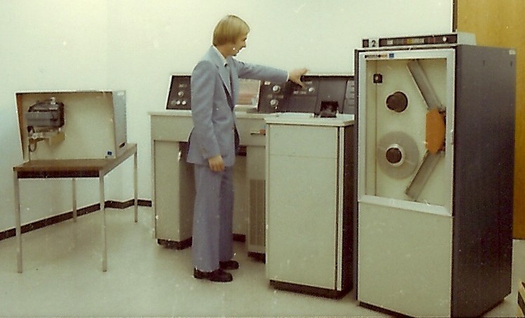
What science fiction movie would be complete without the computer console
with all the blinking lights? The early Univac military computers were
no different. The front panels had lights for viewing register and logic
bit status for operational and diagnostic functions. Some of these also
had integral push switches for inputting data manually so the computers
could be single-stepped thru each operation. Some modules had no indicators
and were only push switches. {Editor's note: At the right is a 1950s
photo of Jack Smith showing Athena panel functionality to Noel Stone.}
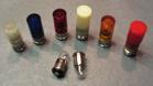 The indicator/switches, used for many years
on Univac military computers and peripherals, were contained in cylindrical
modules that were mounted in round holes in computer front panels using
a lock washer and knurled ring nut. There were electrical terminals
on the rear of the modules for connection, via wire, to the computer
back panels. Early lighted modules used 10V to 28V incandescent flange
base lamps. When
the lamps burned out, they were replaced by unscrewing the indicator
lens and pulling out the pressed-in lamp. [See photo left]
The indicator/switches, used for many years
on Univac military computers and peripherals, were contained in cylindrical
modules that were mounted in round holes in computer front panels using
a lock washer and knurled ring nut. There were electrical terminals
on the rear of the modules for connection, via wire, to the computer
back panels. Early lighted modules used 10V to 28V incandescent flange
base lamps. When
the lamps burned out, they were replaced by unscrewing the indicator
lens and pulling out the pressed-in lamp. [See photo left]
The early indicator/switch modules had electrical connection
via what was called a taper pin terminal. The indicator switch had a
tubular post on the rear for each connection. The post was slightly
conical on the inside. The connecting wire was terminated with a split
tapered pin. This pin was pressed into the conical post and, with a
little compression of the split taper, was held in the post by friction
fit. Early machines had problems with intermittent operation in these
connections and thus it was not very reliable.
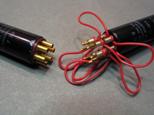 In the mid 1960s, the taper pin system was replaced by a wire wrap system.
The tubular contacts on the rear of the indicator/switch modules were
replaced with gold plated square posts 0.045 inch on a side and 0.5"
to 1" long depending how many wires were to be attached. A special wire
wrap tool wrapped several turns [one layer] of the connecting wire around
these posts. The wire wrapping tightly around the corners of the square
posts provided a significantly more reliable connection. [See photo
right]
In the mid 1960s, the taper pin system was replaced by a wire wrap system.
The tubular contacts on the rear of the indicator/switch modules were
replaced with gold plated square posts 0.045 inch on a side and 0.5"
to 1" long depending how many wires were to be attached. A special wire
wrap tool wrapped several turns [one layer] of the connecting wire around
these posts. The wire wrapping tightly around the corners of the square
posts provided a significantly more reliable connection. [See photo
right]
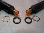 Shortly after the wire wrap technique was implemented,
we [component engineering] were advised by manufacturing in plant 3,
that the indicator/switch modules were rotating in the front panels
thus misaligning the contact locations. This rotation was caused by
the applied torque of the wire wrap guns. I [Larry Bolton] was invited
to the manufacturing floor to witness the problem. I determined that
the problem was allowed due to the use of an internal fine-tooth lock
washer between the body of the module and the rear of the front panel.
The
teeth of the washer were not engaging the front panel but were merely
inside the front panel mounting hole. After a little investigation,
I determined that an external tooth lock washer would be more effective
since it would bite into both the edge of the module and front panel.
Although the teeth were visible, this was not a problem since it was
inside the cabinet. From that day on, all wire wrapped front panel indicator/switch
modules used external tooth lock washers. [See photo left]
Shortly after the wire wrap technique was implemented,
we [component engineering] were advised by manufacturing in plant 3,
that the indicator/switch modules were rotating in the front panels
thus misaligning the contact locations. This rotation was caused by
the applied torque of the wire wrap guns. I [Larry Bolton] was invited
to the manufacturing floor to witness the problem. I determined that
the problem was allowed due to the use of an internal fine-tooth lock
washer between the body of the module and the rear of the front panel.
The
teeth of the washer were not engaging the front panel but were merely
inside the front panel mounting hole. After a little investigation,
I determined that an external tooth lock washer would be more effective
since it would bite into both the edge of the module and front panel.
Although the teeth were visible, this was not a problem since it was
inside the cabinet. From that day on, all wire wrapped front panel indicator/switch
modules used external tooth lock washers. [See photo left]
The lighting in the modules also changed over the years. Initially the lights were either the incandescent type mentioned above or a higher voltage neon lamp. The neon lamp was not replaceable. The light emitted from these was white or yellow. The lenses on the indicators were colored red, green, orange, blue, white, or were clear. Some modules had integral transistor lamp drivers to turn the high voltage lamps on or off [the signal being brought in was a logic level signal]. Later, the modules used light emitting diode (LED) technology. The use of the LED allowed use of smaller indicator lights. Use of these individual indicators continued through the 1990s with use on UYK-43 and UYK-44 maintenance panels. The individual indicator lights were made mostly obsolete due to the evolution into CRT (cathode ray tube) and LCD computer display screens with alpha-numeric displays.
These indicator/switch modules were made
by Dialight and a local startup company called Transistor Electronics
Corp. (TEC). [Larry D. Bolton ]
![]()
5. Embedded Processing and Communications by Harry Wise
The up grade to the 69B display system, this buried a PC in the old box. The PC was designed under Tom Ericson. It was the first PC design using the new “Topcat” chipset. Today every PC uses a chipset but I think this was the industry first. We tried to sell it to the Unisys Framington operation that was building a PC for the military. They paid a heavy royalty for a motherboard design from a Japanese firm on every system and lost money like mad. It was a poor design and expensive to build. We said that we would re-layout our mother board to industry standard format and deliver three prototypes for $50,000. [I think we said 3 months.] This would have saved $29,000,000. [I said that they were losing money like mad] Framington wanted to do it themselves. They shut the plant before they ever produced a revised motherboard. The company that we outsourced the BIOS design to used our design and built a business on it for years. I never could document this.
We did a whole series of communications devices. See Joe Pobiel. This was automating “transmitter farms” and “receiver farms”. The full system would have made significant yearly saving in man power in staffing these operations.
One thing we did was to build a remote control unit for the FRT-84 10 KW transmitter. We built over 260 of these. The original design had a remote control unit that did not work. Harris did a redesign that worked but when it failed it cost $30,000 to send it to the factory for a rebuild. These were both “10 U” high and full depth in a 19” relay rack. I had one small board with a Z 80 single chip computer. The bid was $750 per unit which was thought to be impossible. The final figure was about $350. I outsourced the whole build. We did several similar programs including a complete audio and digital switch. “A PBX with the wrong software.” [Harry Wise]
6.0 Computer Aided Design (CAD)
In response to a 2007 request from the Legacy Committee, Earl Vraa put together a summary of our company's history of Computer Aided Design. He had inputs from many other individuals who were developers of Automated Design systems software. He references three previous topical papers as supplemental sources:
- Reprint of A PROGRESS REPORT ON COMPUTER APPLICATIONS IN COMPUTER DESIGN by S. R. Cray and R. N. Kisch - circa 1954, provided by E.M. Vraa.
- Computer Aided Design - What is Worthwhile by Earl M. Vraa et al. from 1972
- A System Through Hardware Design Methodology by Larry D. Anderson and Earla - circa 1986
We've posted these three papers as 'Article for the Month'. This CAD history isn't a complete story yet - there are some 'holes' as memories of the developers have waned. We welcome readers comments and inputs for a follow-up paper. One supplement already here are the experiences of Michael Pluimer - http://vipclubmn.org/Software.html#Simulations. [LABenson]
 Now, in 2022 Earl Vraa and Jim Andrews are collaborating on yet another CAD history initiative.
For example the Autogram Display and the role it played in the
development of the 1110 computer systems.
Now, in 2022 Earl Vraa and Jim Andrews are collaborating on yet another CAD history initiative.
For example the Autogram Display and the role it played in the
development of the 1110 computer systems.
In this Chapter
- Introduction
- History Tidbits from Frank Kline
- PC Design by Bob Langer
- Maintenance Panels by Larry Bolton
- Embedded Processors and Communications by Harry Wise
- Computer Aided Design (CAD) by E. Vraa, et al.
Chapter 40 edited
7/25/2025.
![]() |
Home, Pg 1 |
Our Legacy, Ch 1 |
People |
Locations |
Engineered |
Computers |
Systems |
Contacts and Links |
Site Map, Pg 0 |
|
Home, Pg 1 |
Our Legacy, Ch 1 |
People |
Locations |
Engineered |
Computers |
Systems |
Contacts and Links |
Site Map, Pg 0 |
Copyright ©2025, LABenson for the VIP Club. All Rights Reserved; Hosted on www.webhostinghub.com since 2011.