

Information Technology (IT) Pioneers
Retirees and former employees of Unisys, Lockheed Martin, and their heritage companies
Peripheral Engineering, Chapter 47
1. Introduction
As systems evolved, there was always a need for special equipment
to interface with computers, as printout devices, operator control,
and input devices. Sperry Univac had standardized the electrical
interfaces between equipment per its
publication PX3494, a formalization of our Design Specification
4772 which became the foundation for the Government Mil-Std-1394.
Many of the defense industry software development centers needed peripheral
support that wasn't used in ruggedized environments. Several centers
used the UNISYS Commercial 1004 and/or 9300 systems for punch card reading,
card punching, and printing as well as card to tape copying for compiler
inputs. As displays replaced the maintenance panel buttons, programmers
were quite active in developing graphic User Interfaces (GUI) which
were used by operators. There was a point in time that we started to embed micro-processors
into displays so that with communications links, they became the processors
or the programmable smarts of the systems.
We're looking for people to write about the ICKCMX and other equipments developed for our systems as well as any Graphic User Interfaces (GUI). [lab]
2. Data Exchange Auxiliary Console - OJ 172 by Dick Kuhns
The delivery of the first UYK-7 Computer in 1969 marked
the introduction of a new generation of computer systems for the U.S.
Navy. In the same time frame the Navy contracted with Sperry Rand to
define and develop the Data Exchange Auxiliary Console (DEAC). The DEAC
was intended to provide input/output support to the AN/UYK-7 computer
systems, combining into one cabinet a paper tape reader and punch, a
keyboard/printer, and two magnetic tape transports. These functions
formerly occupied two cabinet configurations, and the Navy wanted the
same functions in one cabinet occupying much less space.
I initially became involved with the DEAC during the development of
the requirements specification. The U.S. Navy produced a first draft
specification by merging specifications for the previous equipment without
much change. We had a team of people performing IR&D on defining
performance requirements for a next generation magnetic tape unit during
the same time period. So I went to Washington DC for a few days to help
revise the specification to include new I/O Console performance requirements
visualized by Engineering’s latest thoughts.
Once we had a requirements specification we launched a pre-proposal
and proposal phase to design and bid on the DEAC. The most significant
challenges faced by our design team were arriving at a compact physical
configuration and the selection of a Magnetic Tape Transport (MTT).
The selection of a compact MTT was key to a compact physical configuration.
The traditional MTT use by NTDS was a unit produced by Potter and used
tension arms as a tape buffering mechanism. Tension arms had the disadvantage
of causing excessive wear of the tapes at times. Potter did not have
a suitable MTT fitting the new requirements. Engineering decided to
work with Sperry Flight Systems (SFS) in Salt Lake City to develop a
new MTT from scratch. The development of a new MTT was a risk factor
for the DEAC development; but, SFS succeeded in developing a very good
compact unit using vacuum loops as tape buffers. {Editor's note: The
1840 magnetic tape unit previously developed by SLC in 1969/70 for the
German Navy's FPB had proven the vacuum loop operation technology. This
technology was later used on the commercial Uniservo units.}
The final form factor for the DEAC resulted in a unit that was a little
tall with the Keyboard/Printer located on top of the cabinet. A short
person needed a little help to reach the keyboard. The project officer,
CDR Drenkard, for the U.S. Navy was very tall and so was not troubled
by the height of the console.
An interesting side note during the development of the DEAC involved
a test lab engineer's perception of the unit’s capability to withstand
shock and vibration requirements. It so happened that the test engineer
was originally on Wernher von Braun’s NASA rocket development
team. I only remember him as Rudy. Rudy had a model he used to analyze
an equipments capability to meet shock and vibration requirements, and
the model showed the DEAC cabinet would not meet requirements. A decision
was made to build a mockup of the DEAC and subject it to shock testing.
The unit easily passed the shock and vibration tests so Rudy updated
his model and the DEAC became the primary input output peripheral equipment
use by UYK-7 systems in the 70’s and 80’s. {Editor's note:
Rudy also supported the MIL-E-5400 vibration testing of the CP-901 at
the SLC facility in 1968 as well as at the Brigham City, Thiokol facility.
He was originally from Yugoslavia - had been a partisan during WWII.}
By Lyle Franklin - On one of my first trips to DC I was given a drawing for the DEAC by Don Vizanko to deliver to CDR Carl Drenkard. I looked at the drawing. It looked like a 1532 leaning against a 1540. I did meet with Carl and later we had lunch. I didn’t show him the drawing. We discussed his goal for the JEEP system as well as his requirements for the DEAC. His main concern was floor space. I explained to Carl there was nothing behind the tape handlers and to reduce the size they would have to be mounted sideways in drawers. Carl’s comment was the programmers were used to seeing the tapes moving. I mentioned that these would be aboard ship units and programmers would not be using them. I also mentioned we could put lights on the drawers, red for backwards, green for forward. I laid out the concept on a napkin and Carl showed interest. Upon my return to St. Paul I met with Phil Skubitz, mechanical engineer, and he put in correct dimensions what later became the DEAC. As Carl was more concerned about floor space he was pleased that finally he wouldn’t have to bend over a piece of equipment. Univac was the first to put a rotating memory storage unit in a drawer. Due to the innovative approach Carl was able to justify a sole source award.
3. Input/Output Consoles - commercial
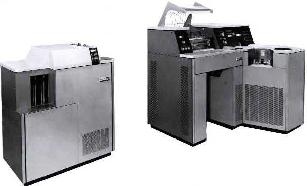 1004 Printer, Card Reader, and Card Punch
This system manufactured by UNIVAC commercial operations had a plug board to set up the sequence of operations. The Plant 1 Military Computer Center had one of these units when I worked there from 1963 to 1966. With a bit of manipulation of the plug board, we could change the card ID and number while duplicating card decks. This allowed programmers to re-use subroutines within new programs before compiling.
As operators, we most often used this unit to provide programmers with listings of their source code. That center used the SS-80 (with a drum memory for programs and data) for the card to tape and tape to print functions.
 4. Input/Output Consoles - ruggedized.
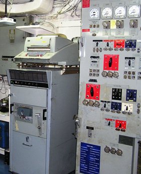
An upright 1532 is shown at the left in a shipboard installation. The keyboard/printer mounted atop this unit is a model 35 teletype that used ASCII code. The paper or Mylar tape programs were coded, i.e. if the tape began with a '76' the following instruction code was an absolute load, i.e. immediately behind the 76 was the beginning address and count. The end of the tape had a checksum. If the tape began with a '75' then the instruction code was a relative load, could be used as a relative addressable routine in the computer.
 The 1289
teletype unit is shown at the right. This unit was used for ship to
ship and ship to shore communications for the Naval ships.
The 1289
teletype unit is shown at the right. This unit was used for ship to
ship and ship to shore communications for the Naval ships.
5. Magnetic Tape Units
PX 899 illustrates the Remington Rand Univac UNISERVO mechanical parts. The Uniservo units were part of the commercial computer systems developed both in Blue Bell and St. Paul's Roseville operations.
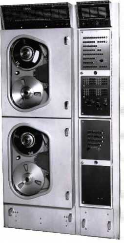 5.1 1540 by Lowell Benson
At the left is a photo of the 1540 two handler magnetic tape handler which is in the San Diego NTDS shipboard museum. Thanks to Jon Simon for this snapshot.
5.2 1840 by Lowell Benson
Field Service's Al Rudman and I were the installation engineers in Hengelo, Holland when the first German Navy 1840 magnetic tape unit with transports S/N 1 and S/N 2 was delivered from the Salt Lake City plant. There were three problems with it!
- The unit was in a wooden crate on a pallet. We carefully pried off the top and one side of the crate's frame and cut into the wrapping and packing. Atop the unit was a technical booklet and a sheet with 'unpacking' instructions. Had we had the 'unpacking' instructions - we would have just tilted the pallet to unbolt from the bottom then lifted the crate off of the unit.
- The POFA test program was on a magnetic tape, however we didn't have a loader to load from the 1840. I read the code from the listing, extracted some simple routines, then with the help of Jim Gannon [programmer] and Al Rudman [field engineer] put together a simple test to interface with the unit. Nothing that we tried would work - we knew that it had worked before being shipped from Salt Lake City. Al and I wrote an even simpler sequence of code to just send a series of commands to the 1840 controller. This resulted in one of the tape drives seeming to jerk but not run. After refining the check code, we started to probe signals from the 1830B in the 1840 controller. The signals didn't make sense. After about an hour of probing and noting, I realized that the 85 pin connectors on the control unit had been wired using the pin assignments of the old 90-pin hammer head connectors - the same as the 1240 and 1540 tape units had been wired {reference DS4772 - predecessor to MIL-STD-1397}. Having had experience of changing or fixing 85 pin connectors during CP-901 and 1830B checkout, I rewired the tape units' controller interface. Reconnected; the simple test program then could select either transport, could write a test pattern, rewind, and read. We were then able to run the POFA and provided a 'bootstrap' program back to St. Paul so that they could update the 1830B's core rope to load from the 1840. Then I wrote an Engineering Infomation Request to change the wiring [just happened to have a form in my briefcase] and sent it to Salt Lake to get the wiring in following units correct. SLC at first was a bit upset that an engineer in the field would try to tell them what to do - our on-site boss, Ernie Lantto, got on the phone and soothed their feathers. They then accepted the change.
- The tape units used LEDs on one side of the tape vacuum columns and sensors on the other side to determine tape loop positions. These vacuum columns were used instead of mechanical tension arms to inhibit tape jerking during drive motor start and stop actions. After a couple of weeks, we started to have a series of tape failures. The software was setup to check read blocks after writing - if both a first and a second attempt to write a block failed, then a third write using an extended inter-record gap would be tried. This seemed to help a bit, but we were still having problems. We used a talc like substance on the magnetic side of a couple of failed tapes, detecting that the tape itself had some fair sized bubbles. This led us to discover that when a tape section 'sat' for more than 15 minutes in one of the vacuum columns, heat from the adjacent LED was causing the tape to deform at that spot. We disassembled one of the transports, installed a couple of small washers with longer screws to move the LED back from the column surface by about 1/8th of an inch. Then we increased the sensitivity of the opposite side sensor - the tape transport tape tension system then didn't deform the tapes. I sent a Request For Change to SLC asking for a better solution then my 'jury' rig method.
Now the rest of the story: The Dutch, who were the prime contractor for the German Navy, were absolutely flabbergasted that a 'simple field engineer' had the authority to make 'design changes' to equipment, much less tell the factory what to do. Again, Ernie ran interference for a brash engineer who had the make-it-work attitude. [As a side note, the Dutch programmers actually had their program design flow charts done in ink before writing any code.] A couple of months later, I was asked to assist Woody Knight in a meeting with the German procurement agency in Koblenz Germany as he was negotiating follow on units. I don't recall who else from UNIVAC was there but do recall the German buyer stating: "We really were the 'guinea pigs' for those tape units, weren't we."
In a small way, I like to think that my experiences and feedback
to SLC helped to make the RD-358 a good product. Two ways, the 85 pin
connector wiring was then compatible with the 'new' AN/UYK-7 Navy standard
computer connectors and the tape transports didn't wreck the tapes.
![]()
5.3 RD-358 by Lyle Franklin
After taking over most of Navy Marketing, I met with Erick Swenson
at NAVSEC. Potter, our supplier of tape handlers had gone belly up.
Also we had been trying to replace the 1540’s. I asked Erick why
he didn’t like the German magnetic tape units [1840s.] Being Erick,
he said he told Univac his problem but we didn’t listen. Finally
he agreed to tell me the problem. He had 37” of floor space. He
wanted four handlers. The German units were two handlers 24” and
he didn’t have 48”. We discussed the Salt Lake City handler
and the auto load feature. Upon my return to St. Paul, again I called
upon Phil Skubitz and laid out five configurations for him to design
and fit into 37”. Knowing Erick, I reviewed Phil’s drawings
and we put the current configuration in third place in the package.
Ray Smith delivered the configurations to Erick. Dick Seaberg, Marlin
Wagner, and I met with Erick when Erick came to St. Paul. This was Dick’s
first meeting with Erick since he became head of Marketing. Dick had
been briefed that Erick would select configuration 3 and also complain
that marketing should have had that one on top. Sure enough, it happened.
Previously Red Phillips had agreed to help fund the St. Paul effort
as a business plan expense. The acceptance was contingent on Erick’s
review of the SLC handler. I met with Erick in SLC and the RD-358 became
a done deal.
![]()
6. Display Units
6.1 1562 Display:
The nomenclature is: UNIVAC PLASMA GRAPHIC DISPLAY - TYPE 1562-00, SERIAL NUMBER 1
There are many images of the unit here: http://www.bunkerofdoom.com/computers/univac/1562/index.html from Patrick Jankowiak
The plasma display was provided to E-Systems for an Electronic Warfare system on USAF EC-135's in the 1970's. I'll think of the name in a bit. The processor onboard was the AN/UYK-15. All development work was done at the E-System airfield in Greenville, TX and testing/operational out of Offutt AFB, Omaha, NE. The displays were built in Plant 1, St. Paul and we probably built about 10 of them; that's how many KC-135's were outfitted with the system. John Westergren
1) 1652 is a type number in the old Sperry system, and I believe we have some old type and feature catalogs in the archive. Timing is fortuitous, as we can check tomorrow when we're in.
2) We did have a contract with E-systems around the 1616/UYK-15 timeframe (Counter mortar and counter battery comes to mind.) I believe Jack Lavers was the PM.
3) Some work was done with plasma displays in the late 60's - notable
one was a transparent Owens Illinois plasma displaying digital data
over an analog CRT for Polaris or Poseidon. Early way to integrate analog
and digital. I think Dave Kirkwood was involved from a technology standpoint,
Al Kaczynski from engineering.
Harvey Taipale
![]()
6.2 AN/USQ-69:
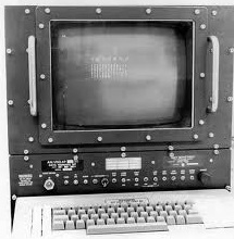
In the late 1970’s personal computers (PC) were only just in
their infancy after being conceived by many like Bill Gates and Steven
Jobs. The engineers at the Naval Electronics Command (NAVELEX) came
to Sperry Univac,
providers
of the Navy’s UYK-7 standard large scale computer and UYK-20 standard
small scale computer to see if a personal computer could be designed
and built for usage aboard the Navy’s ships and submarines. Years
later laptops and Panasonics' Toughbook© are as common
as telephones, smart-phones, and tablets, but in the 1970’s, there
was nothing like a PC that could survive the rigors of an at sea environment.
The USQ-69 was designed, developed, and produce to do just that.
Although developed as a 'ruggedized personal computer', the Navy
chose to assign its' nomenclature as a display - according to Duane Craps: "The AN/USQ-69 was only a terminal.
Today it is relatively easy to purchase all of the
needed PC components off-the-shelf and almost anyone can assemble their
own should they choose; not so in the late 1970’s. Intel’s
8086 microprocessor wasn’t on the market until 1978 and Motorola’s
68000 until 1979, so when the Univac engineers designed the processor
for the USQ-69, they basically started from scratch with simpler available
microcontrollers and created a processor for a PC.
Operating
Systems (OS) for PC’s were very simple disk storage management
systems (the first Windows© operating system wouldn’t be provided
by Microsoft until the mid-1980’s,) so the OS for the USQ-69 also
had to be created by Univac programmers.
The USQ-69 is another example of how the Navy envisioned technology
to meet their ever evolving mission requirements and the people of the
Lockheed Martin and Unisys legacy companies in Minnesota responded with
products to meet that need. [from John Westergren]
![]()
6.3 AN/UYQ-70:
This section has been moved to Chapter 58, section 3.5.
7. Repertoire Cards
Many of our retirees donated repertoire cards to the Legacy Committee. Keith Myhre scanned and catalogued these at the Lawshe Memorial Museum. The 1st copy was donated to the Charles Babbage Institute, a second copy of many was kept at the museum.
- Transtec II and Magstec II Repertoire of Instructions with Flexowriter codes. Included on this page because of the Flexowriter.
- Sperry ACS PDS Uniscope Access
- Sperry Magnetic Tape Unit Codes (RD-358, ..., DEAC)
- Sperry Rand Univac Input Output Codes (1004, 1232, 1532, 1240, 1540, ... )
- Sperry Univac ACS PDS Uniscope Access
- Sperry Univac Engineering U100 Display Codes
- UNIVAC 1004 80-Column Code
- UNIVAC Defense Systems Training I/O Codes (1232, Flexowriter, Teletype)
- UNIVAC Education Department Input Output Codes (1004, ...
- UNIVAC Keyset Central Digital Data Converter (CV-1123 USQ-20(V) & RD-243 ...)
- UNIVAC I/O Codes (Flexowriter, 1232, ...)
- UNIVAC Magnetic Tape Units Comparison
- UNIVAC NTDS Teletypewriter Codes
- UNIVAC Reference Card (processors & peripherals in the Plant 1 Military Computer Center)
8. Technical Manuals
The bit-savers web site [http://bitsavers.informatik.uni-stuttgart.de/] has over 32,000 documents. We've copied the peripheral equipment documents that we recognized and then linked them hereunder for technology researchers ease of access.
- PX616 UNIVAC High-Speed Printer Description
- PX1107 On-Line Input/Output System for the FAA
- PX3221 UNIVAC 1240 Magnetic Tape Unit Technical Description
- U4465 UNIVAC 1004 III Magnetic Tape System
- UNIVAC High Speed Printer
- UT3408 UNIVAC Uniservo IIIC tape drives used with 1107 systems.
In this Chapter
- Introduction
- DEAC by Dick Kuhns & Lyle Franklin
- I/O Consoles - commercial
- I/O Consoles - ruggedized
- Magnetic Tape Units - 1540, RD-358, & 1840
- Display units
- Repertoire cards
- Technical Manuals
Chapter 47 edited
7/13/2025.
![]() |
Home, Pg 1 |
Our Legacy, Ch 1 |
People |
Locations |
Engineered |
Computers |
Systems |
Contacts and Links |
Site Map, Pg 0 |
|
Home, Pg 1 |
Our Legacy, Ch 1 |
People |
Locations |
Engineered |
Computers |
Systems |
Contacts and Links |
Site Map, Pg 0 |
Copyright ©2025, LABenson for the VIP Club. All Rights Reserved; Hosted on www.webhostinghub.com since 2011.